What you’ll learn:
- How oscilloscope-based packages improve bring-up, debugging, and validating power converters as well as help engineers achieve faster and more repeatable measurements.
- How analysis software can help designers overcome typical measurement challenges.
Power-system designers are keenly aware of the sense of urgency surrounding efficiency, density, and reliability these days. For engineers looking to wring out more performance from power systems, measurement software running on oscilloscopes can help at multiple stages of the value chain, including component selection, loss measurement, control system evaluation, and pre-compliance testing.
Power measurements involve multiple probes and calculations. Setups can be complex, but analysis software on today’s oscilloscopes helps engineers achieve faster and more repeatable measurements. This article briefly describes three oscilloscope-based packages for bringing up, debugging, and validating power converters such as AC-DC and DC-DC power supplies, as well as three-phase traction inverters and motor drives.
Power Analysis: AC-DC and DC-DC Converters with the 4 Series B MSO
The on-scope analysis packages depend on processing power in the instrument. For example, the new Tektronix 4 Series B MSO, with bandwidths ranging from 200 MHz to 1.5 GHz and up to six analog channels, has a more powerful processor system. Equipped with a full range of power-analysis capabilities at a price point that’s accessible to many professional designers, the 4 Series B is used for illustration in this article.
Several oscilloscope series offer packages for a broad range of measurements on power supplies, turning them into ersatile power-analysis tools. On the 4 Series B MSO, for example, this is called Advanced Power Measurement and Analysis (4-PWR). The toolset is used to conduct measurements on AC-DC and DC-DC converters from input stages, to switching stages and control loops, to output stages.
The software automates the setup process for measuring AC line inputs for frequency, RMS voltage and current, and crest factor (voltage and current). It can also process true, reactive, and apparent power, as well as power factor and phase.
Furthermore, the software eases the process of measuring switching loss and magnetic loss in switching converters. These measurements are critical to engineers as they make incremental changes to extract out fractions of a percent improvement in efficiency. The software also allows for the in-circuit measurement of safe operating area (SOA) for switching devices. Bode plots can be used to evaluate the stability of power-supply control loops.
Devices based on wide-bandgap (WBG) materials such as silicon carbide (SiC) and gallium nitride (GaN) switch significantly faster than their silicon counterparts, taxing the capabilities of many measurement systems. Accurate characterization of switching performance requires much higher measurement bandwidth to accommodate these higher slew rates.
Double-Pulse Testing for WBG Devices Using Advanced Software and IsoVu Probes
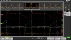
Special analysis software for double-pulse testing is available to help designers make the transition from silicon to WBG switching devices (Fig. 1). This software automates setups, makes measurements, and performs calculations. For example, Tektronix’s double-pulse testing software includes a special deskew algorithm to facilitate the alignment of current and voltage signals, which is critical to achieving accurate results. Automated measurements include turn-on/turn-off energy, reverse-recovery time, and reverse-recovery charge, among others.
Probing is also an important consideration for gate-drive measurements. Until recently, switching measurements on the high side of half-bridge switching stages were almost impossible. Any measurement relative to the switching node suffered from distortion due to the high-common-mode voltage signals impinging on the differential signal.
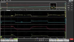
This challenge was the inspiration for the development of a class of probes in the IsoVu probe line that uses optical isolation to achieve common-mode rejection of 80 dB at 1 GHz and higher at lower frequencies. The IsoVu optically isolated probes are compatible with the 4 Series B MSO. With these probes, the 4 Series B can measure switching signals of 100 V/ns or faster (Fig. 2).
Drive and inverter designers can also benefit from scope-based measurement and analysis software. Most modern motor-drive systems use pulse-width modulation (PWM) to control the frequency and therefore the speed of a motor. PWM makes stable measurements on these signals challenging, though. Determining the right combination of filters and triggers to achieve stable waveforms without the assistance of analysis software can be daunting.
Motor-Drive Analysis: Overcoming PWM and Three-Phase Challenges
Making the challenge more formidable, motor-drive systems often have three-phase inputs and outputs. This complicates connections and setups. The wiring configuration determines the calculations used in power analysis. Therefore, it’s important to understand and select the correct wiring configuration to obtain useful results. Incorrect probing of the motor-drive system and poor integrity of connections are common sources of errors in making motor drive measurements.
On three-phase systems, measurements such as power, power factor, phase and harmonics involve a fair amount of calculation. Exporting raw waveforms into a spreadsheet or other analysis software is possible, but the process is time-consuming and care must be taken when performing calculations.
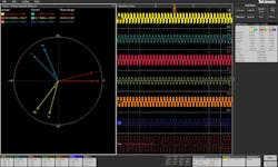
Analysis software can help designers overcome the challenges noted here and get an accurate view of a motor-drive system by automating setup, achieving stable waveforms, and applying proven measurement algorithms. One example of three-phase power analysis software for an oscilloscope is the 3-Phase Analysis package on the 4 Series B MSO (Fig. 3).
One more consideration regarding three-phase systems is that the output of many motor drives and inverters are three-wire systems. They either don’t have a neutral conductor, or the system is balanced and there’s no neutral current.
Power in these systems can be accurately measured by using just two voltage channels and two current channels, leveraging the two-wattmeter method. In this approach, two voltage channels are connected from phase to phase, with one of the phases acting as a reference. Two currents are measured on the two non-reference phases. Thus, power can be measured with a four-channel oscilloscope.
However, the inputs to an industrial variable frequency drive (VFD) are more likely to use a four-wire system, which includes a neutral conductor. In this case, three wattmeters should be used. This requires six oscilloscope channels—three for voltages and three for currents. Although several oscilloscopes are equipped with eight input channels, the 4 Series B MSO is available with six analog inputs.
Faster Measurements with Scope-Based Analysis Tools
Oscilloscope-based analysis tools for power-converter measurements, double-pulse testing, and three-phase measurements assist designers in making fast, repeatable measurements. The new wave of industry products, such as the 4 Series B MSO, with its faster processor, available bandwidths, and six input channels, provides a solution for power-analysis work.
Read more articles in the TechXchange: Oscilloscope Techniques.


