This file type includes high-resolution graphics and schematics when applicable.
In a bid to satisfy continually increasing demands for higher performance, communications-equipment providers are moving to higher speeds on their internal printed-circuit boards (PCBs). Currently, 28-Gb/s signal rates are in design phases, with 56- and 112-Gb/s rates in the future.
The challenge is that PCBs aren’t well-suited to handling these higher speeds—they have issues with signal integrity (noise, insertion loss, amplitude, etc.), and that limits the distance PCB traces can reliably carry a high-speed signal. As a result, PCB designers must cope with board-layout limitations or move to higher-performing but more expensive PCB materials.
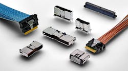
Mid-board copper (MBCu) solutions use connectors and cable assemblies to address this challenge. By bypassing the PCB, an MBCu solution delivers greater design flexibility, lower costs, and much better signal-integrity performance. With a cable that can extend to any component inside the box or even to external devices outside the box, an MBCu connectivity solution turns a two-dimensional circuit-board design into a 3D space where far more configurations are possible.
Design Considerations
Designers should think through several criteria when considering a mid-board copper solution, including flexibility, signal rate, insertion loss, distance, connector configuration, and cable type.
Flexibility
Designers have to deal with nearly 30 different connector standards, including PCIe, SAS, SATA, Ethernet, and InfiniBand. It’s painful to consider using a different connector for each standard, but this has been the practice until recently. Now, it’s possible to use one connector design to support all standards. To meet this requirement, the MBCu solution should:
• Work across a range of data rates, from 8 to 112 Gb/s.
• Use standard manufacturing processes.
• Offer both vertical and horizontal connection options.
• Offer a range of pin-configuration options to address all design needs.
• Accept a cable connection to take the connector from a 2D to a 3D solution that allows flexible connectivity to components and devices both inside and outside the box.
• Be cost-effective enough for lower-performance applications, yet high-performance enough for higher-speed applications.
Signal Rate
While PCBs may be fine for transporting signals up to 10 Gb/s, they begin to limit performance at higher speeds. Designers can use MBCu solutions to increase their HPC capabilities because they can put a connector right next to a processor and drive signals as fast as the IC can handle. With this solution, the PCB is no longer a bottleneck to performance.
Insertion Loss and Signal Integrity
Designers can only put up with so much insertion loss before the PCB traces have to get really short—less than four inches to go from a connector to an IC. A mid-board copper solution eliminates this restriction because you can use a cable to take a signal quickly and reliably as far as you need to take it.
Whenever you’re routing signals through traces on a PCB, there are a lot of traces. When routing the traces through all of the components, you have to be cognizant of the signal integrity, and you need to do extra signal-integrity analysis to ensure proper performance. Using a cable eliminates signal-integrity issues.
Distance
MBCu solutions come with various gauge cables, but all deliver signals over greater distances than PCBs. For example, a 33-gauge cable typically delivers a 4X savings in insertion loss; with larger cables (30-gauge or lower), the insertion loss improvement will be even better. As a result, a design that enforced a limit of four inches using a PCB can now extend 16 inches using an MBCu with a 33-gauge cable. This promotes design flexibility and simplifies the PCB layout.
Connector Configuration
In a solution with a 0.6-mm pitch, the plug-in card that goes into it uses standard PCB technology. When you move to a MBCu product with a 0.5-mm pitch, you can’t use current PCB technology that’s typical to the industry. You either have to use a two-piece connector, or opt for more expensive ball-grid-array (BGA) laminates utilized for very tight applications. Also, you should decide whether vertical or right-angle connectors are needed—this will depend on the application. A solution that offers both vertical and right-angle connectors will give you more flexibility.
Cable Type
MBCu solutions should offer a choice of cable types: ribbon cable or Twinax. Ribbon cable is used for lower-speed applications like PCIe or SAS. If the design requires a 28-Gb/s or higher-speed signal, it will most likely employ a discrete Twinax cable.
Advantages of Mid-Board Copper Solutions
An MBCu solution, which offers flexibility and overall cost savings, provides a unified, high-performance platform to use for a variety of interconnects in a system. Rather than use one connection for a card edge and another connection for a cable and a third for a socket, designers have one platform that can function in multiple places. This helps simplify and streamline the qualification and design processes. In addition, MBCus offer a cost-effective alternative to optical connections—an optical module might cost 6X to 7X more than MBCu cabled solutions.
As equipment makers move to higher speeds on their PCBs, MBCu solutions are becoming an attractive alternative for carrying signals within a system, delivering greater design flexibility, higher performance, and lower costs. By selecting an MBCu solution that meets all applications, manufacturers can save design time and costs.
Arash Behziz is a business development manager and technologist for the Data and Devices business unit of TE Connectivity.


