This file type includes high-resolution graphics and schematics when applicable.
Embedded developers have never had more standard board or module options than are available now. Standard form factors like PC/104 continue to grow in popularity, packing in more interfaces and computational support while vendor-specific form factors provide developers with even more options.
Expansion options have likewise expanded into a plethora of alternatives from Mini PCIe (see “PCI Express Mini Card Tackles Compact Embedded Expansion”) to stackable interfaces like PC/104 OneBank and SUMIT. Perhaps the biggest change has come in non-volatile, on-board memory. Flash memory options include soldered eMMC modules to removable MicroSD slots. Rugged Mini PCIe sockets often support mSATA devices. They also have a USB and I2C interface that are often utilized.
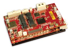
Compact devices like VersaLogic’s Osprey (Fig. 1) Embedded Processing Unit (EPU) are ideal for mobile applications like UAVs where performance and low power are critical requirements. Vendor-specific platforms like this allow more compact designs.
The Osprey EPU is only 55 by 95 by 27 mm, but it packs a wallop, including Intel’s quad-core Bay Trail processor with up to 4 GB of DDR3L memory and up to 8 GB of eMMC flash memory. Storage options include a MicroSD slot and a SATA port. It has high-speed connectivity including dual Gigabit Ethernet ports and USB 3.0 connections. Expansion is possible via a full-size Mini PCIe socket with mSATA support and a half-size Mini PCIe socket. Video outputs include DisplayPort++ and LVDS connections. The conduction-cooled system requires less than 7 W of power.
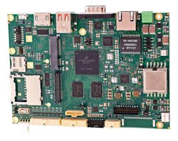
Standard ARM-based parts have provided vendors with low-power alternatives to the x86 world. WinSystems’ SBC35-C398DL (Fig. 2) runs NXP’s 800-MHz i.MX 6DL SoC, which has a pair of ARM Cortex-A9 cores. It also supports ARM’s TrustZone security features. The board is a popular 3.5-in. form factor with expansion options that include support for a half-size Mini PCIe card and an IO60 expansion connector. It can be powered by a Power-over-Ethernet (PoE) connection via the Gigabit Ethernet, which also has IEEE-1588 support or by a 10- to 50-V dc source.
The SBC35-C398DL holds up to 2 GB of DDR3 DRAM and a MicroSD slot. It also has a CMOS camera input, six USB 2.0 ports, 24 GPIO lines that are 30 V tolerant, HDMI and LVDS video outputs, as well as audio support. The IO60 connector exposes I2C, SPI, GPIO, and PWM signals.
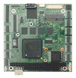
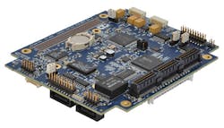
Vendors have been able to pack more onto a board as system-on-chip (SoC) designs pack more into a single chip. Likewise, the use of low-power, compact FPGAs provides flexibility that vendors can take advantage of without having to expose users to the complexity of FPGA programming. The challenge these days is often how to connect these interfaces to the outside world. Some designs, like Diamond Systems’ Helix (Fig. 3), allocate almost half the board to connectors.
The Helix is a stackable PC/104 design with a 1-GHz, x86-based DMP Vortex86DX3 SoC with up to 2 GB of memory. It has six USB 2.0 ports, two RS-232/422/485 and two RS-232 ports, a 10/100-Mb/s Ethernet port, a 1 Gigabit Ethernet port, and a SATA port that can be used with an on-board SATA DOM or off-board SATA device. A Mini PCIe port support mSATA. CANbus 2.0 is a custom option.
There is a 16-channel, 16-bit ADC with a 100-kHz sample rate plus four 16-bit DAC channels with voltage outputs. There are 11 programmable digital I/O lines. These peripherals are supported by Diamond’s Universal Driver data-acquisition programming library plus an interactive, easy-to-use graphical control panel that runs on Windows or Linux to provide to control of all data acquisition features.
The PC/104 ISA bus is not fast compared to PCI Express (PCIe), but it is much easier to design an expansion board for ISA. Many applications can make due with ISA’s speed and memory limitations typically reducing the cost of custom or standard expansion boards.
Compatible form factors like EPIC and EBX use a larger processor board, allowing more peripherals and connectors to be incorporated in the base system while providing stacked expansion.
PCIe Stackables Blend Expansion and Compactness
PC/104-Plus added a PCI connector to the mix with its higher performance and functionality. Having two connectors on either side of the board provides a rigid stack, but it does take up board space.
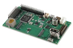
A PCI-only, PCI-104 variant is a standard configuration freeing up board space (Fig. 4), but even PCI has been replaced by PCI Express in most processors and SoCs. Often a PCIe-to-PCI bridge is needed. That type of bridge is straight forward than a PCIe-to-ISA bridge because PCIe was designed based on PCI.
The PCIe versions use a staggered pass-through versus the straight pass-through for the parallel bus PCI and ISA connectors because PCIe is a point-to-point connection. A PCIe expansion board will have multiple lanes coming in. It will route a lane for its use and shift the unused lanes so the next unused lane lines up with the one removed but on the connector on the other side of the board. Normally a single lane is needed for an expansion board. There are x1, x4, x8, and x16 versions.
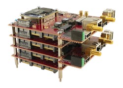
There are a number of PCIe stackable standards. PCIe/104 includes a number of variations including “OneBank,” which refers to the use of one connector bank rather than the three for the full x16 PCIe lane implementation. OneBank can support PCI Express Gen 3. OneBank expansion boards can also work with PCI/104-Express processor boards. OneBank includes four x1 PCI Express lanes, two USB 2.0 connections, and an SMB/I2C interface.
The board on top of the OneBank stack (Fig. 5) from Sundance is the EMC2-KU35. The board supports a range of Xilinx FPGA modules including the Zynq SoC, and Artix and Kintex FPGAs. The board also has an FMC connector to support VITA 57.1 boards. It uses four PCI Express lanes and a 12.5-Gb/s serial link for the FMC connector.
The PC/104 ISA bus was based on early x86 processors. The move to PCI Express platforms opens up this form factor to other processors, primarily ARM-based platforms. ConnectTech’s XTreme/SBC PCIe/104 system board is a carrier board for a COM module (Fig. 6). It currently has three ARM-based COM modules that have an NXP i.MX51, Texas Instruments OMAP, and an Nvidia Tegra in addition to two Intel Atom modules.
The ConnectTech modules contain their own DRAM and flash memory. They have different peripheral complements but typically these include LVDS video, USB, Ethernet serial ports. The Atom and Tegra modules support PCI Express.
Modules Meld Customization with Fast Turnaround
Modules are the flip side to stackables. Modules can be used on standard boards like the ConnectTech Xtreme/SBC, but they are more often mated with custom carrier boards. In general, the carrier board design complexity is significantly less than the module, which is often a multilayer board whereas the carrier is often a two-layer board with connectors instead of dense SoCs.
Developers can often turn to outside design houses to create carrier boards that often incorporate additional peripherals along with the connectors needed to link the system to the outside world. One interesting alternative is Gumstix’s Geppetto (see “Best of 2015: Create Custom Capes Fast and Easy”).
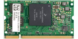
Geppetto is a web-based design tool specifically for creating carrier boards (Fig. 7) including Gumstix's own line of modules. There is a flat set up fee of $1,999 and then a per-board charge. The result is a fully populated board. Geppetto also supports a range of third-party modules as well, such as the Colibri iMX6 SOM (Fig. 8) from Toradex. The Colibri iMX6 is available in dual- and single-core versions. They have an ARM Cortex-A9 core plus 512 MB of RAM and 4 GB of eMMC flash memory.
Modules can range from very tiny boards like the Revolution Robotics' Warp_0x01 module (see “What Is Inside an IoT Chip?”) that targets wearable applications to high-performance modules like Nvidia’s Jetson TX1 (see “Module Delivers Supercomputer Performance”).


