Members can download this article in PDF format.
What you'll learn:
- What's behind the IEEE 802.3cz Multi-Gigabit Glass Optical Fiber Automotive Ethernet standard.
- Optical vs. electrical links in automotive Ethernet.
- Details behind various compliance and conformance tests for IEEE 802.3cz.
- What is TDFOM?
The IEEE 802.3 published the 802.3cz Multi-Gigabit Glass Optical Fiber Automotive Ethernet standard with physical-layer specs and management parameters in 2023. It covers 2.5-, 5-, 10-, 25-, and 50-Gb/s operation over glass optical fiber in an automotive environment. This article will provide an overview of the physical-layer test systems and test requirements as outlined in the IEEE 802.3cz standard.
Why Choose Optical Over Electrical Links in Automotive Ethernet?
Today’s modern vehicles include an unprecedented combination of infotainment systems, advanced driver-assistance systems (ADAS), and computing power. Future vehicles will have even more systems and they’re evolving into a centralized computing platform with many software-defined features.
Cameras and high-definition displays can require upwards of 10 Gb/s, and ADAS sensors are moving from single to tens of gigabits per second. Future software-defined vehicles will share this data between fewer electronic control units (ECUs), thus pushing backbone communications links to ever-higher speeds.
These applications are all enabled by Ethernet, and the industry has responded by creating new automotive Ethernet standards. The most recent multi-gigabit automotive Ethernet standard covers 50 Gb/s over glass optical fiber (IEEE 802.3cz) and 25 Gb/s over copper wire cabling (IEEE 802.3cy).
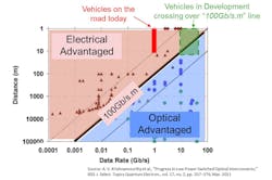
For years, the telecom industry has tracked the product of data rate and distance (data rate × distance) as a metric for system capability. In Figure 1, the distance on the vertical axis and data rate on the horizontal axis and each point represents a commercialized link product.
The brown triangles are copper links that roughly follow a 10-Gb/s*m line. The blue circles are optical links that follow a 1-Tb/s*m line. In between is the 100-Gb/s*m line that’s a common transition point from electron to photon links. While there are exceptions on both sides of the line, this framework holds generally true for many data rates and distance.
A key takeaway supported by this chart is that the minimum successful technology crossover from electrical to optical links, from a commercial perspective, can be represented by a bandwidth–distance product of 100 Gb/s*m. The automotive in-vehicle-networking industry is already shifting to the right in the chart, now reaching close to the 100 Gb/s*m threshold.
For instance, increasing the size and the resolution of the display from 2k to 4k will drive the need for high-data-rate (>10 Gb/s) connection where optical links make more sense. Modern vehicles will absolutely benefit from the bandwidth capability offered by glass optical fiber links.
Within the automotive industry, the general perception is that optical fiber may be fragile and hard to handle in harsh environments. But the reality is that almost all multimode and single-mode optical fibers today are bend-insensitive and can be used in hard-to-reach places without sacrificing performance. Glass fiber-optic cables are very stable in extreme temperature conditions and can meet the most stringent automotive requirements.
Glass optical fiber interfaces offer many benefits over their electrical counterparts. One of the main problems with electrical links is that they’re prone to emitting electromagnetic noise and are susceptible to electromagnetic-interference (EMI) noise, especially as data rates increase. Therefore, electromagnetic-compatibility (EMC) qualification is a critical step in platform validation by Tier 1s and OEMs.
Optical links avoid this drawback thanks to inherent galvanic-isolation characteristics. In addition, optical interfaces provide very little signal attenuation over the long run, making it an ideal solution for long-reach connection. Moreover, fiber-optic cables enable higher data-rate transmission with excellent signal integrity and a lower cable harness weight at lower cost. Automotive applications have evolved and can now derive significant benefit from glass optical fiber technologies.
Compliance Tests and Measurements
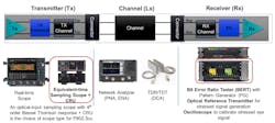
As we build the communication link using the transmitter (Tx), receiver (Rx), and channel segment, it’s important to ensure each component in the system functions well and is compliant with requirements set by industry standards like IEEE. Figure 2 shows the test instruments used.
Transmitters are typically characterized using oscilloscopes, which can be one of two types: real-time oscilloscopes and equivalent-time sampling oscilloscope (or often referred to as “sampling scope”) with a clock recovery unit.
Real-time scopes are widely used in electrical automotive Ethernet physical-layer testing. However, when it comes to measuring optical signals with an oscilloscope, sampling scopes have been used for most optical waveform analyses. They can perform reference receiver testing and bandwidth performance that’s able to keep up with the speeds of fiber optics as well as measurements optimized for optical analysis. For the IEEE 802.3cz multi-gigabit optical automotive Ethernet transmitter and receiver test, the sampling scope is the instrument of choice.
Channels are typically characterized by vector network analyzers (VNAs) or time domain transmission/time domain reflection (TDR/TDT) instruments. Receivers are characterized using a bit error ratio tester (BERT) and/or a pattern generator (PG) from a BERT or arbitrary waveform generator with an optical reference transmitter for converting electrical signals into optical domain to feed into the receiver device under test (DUT). Oscilloscopes are also used for receiver tests, mainly to calibrate the test signal level.
IEEE 802.3cz PMD Transmitter Conformance
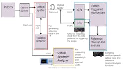
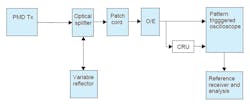
Figure 3 illustrates the optical physical medium dependent (PMD) transmitter conformance test block diagram, which is slightly modified from IEEE 802.3cz.
The test signal coming out of the PMD transmitter output is switched using an optical switch or splitter (1x2) that divides the path to an oscilloscope and an optical spectrum analyzer. When the switch output is set to the oscilloscope, the signal goes through an optical splitter with the variable reflector generating a precision reflection level to determine the influence of reflected power back to the transmitter.
As a result, the Tx is tested with the optical return loss as specified in the 802.3cz PMD characteristics spec. Then, it’s connected to the optical input of the sampling oscilloscope, where a small portion of the signal is fed off to the clock recovery unit (CRU) using an external optical splitter for clock recovery.
The key instrument to consider here is a sampling scope with multimode optical input capable of covering 980-nm wavelength, and the measurement bandwidth required by transmitter test cases. The oscilloscope requires several other capabilities such as pattern lock, impulse response correction, and low jitter time base.
Also needed is a clock recovery unit supporting optical NRZ and PAM4 patterns to recover a clock from the input pattern and using it as a trigger source for oscilloscope. To measure center wavelength and spectral width, an optical spectrum analyzer is required. For all of these connections to the test and measurement instrument, an FC/PC connector is generally recommended.
Critical Test Patterns and Parameters for IEEE 802.3cz PMD
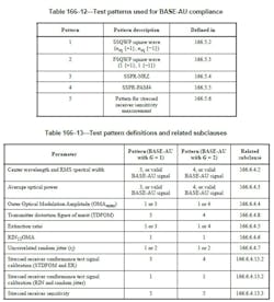
The IEEE 802.3cz standard defines the test patterns used for the transmitter and receiver tests of the DUT PHY (Fig. 4). Depending on the type of the Tx and Rx test, the standard recommends using a different type of test pattern. The basic amplitude modulation scheme for each test is as follows: NRZ for 2.5 to 25 Gb/s, and PAM4 modulation for 50 Gb/s. There are test parameters using those test patterns for each Tx and Rx conformance test.
TDFOM: Metric for Optical-Signal Quality
One significant measurement parameter newly added to the IEEE 802.3cz spec that needs to be highlighted here is transmitter distortion figure of merit (TDFOM). It’s the main metric for measuring the quality of the optical signal transmitted over a fiber-optic cable. It’s also used to guarantee the interoperability of transmitters in terms of signal integrity valid to be received by a compliant receiver.
In addition, TDFOM is applied to calibrate reference transmitters used to measure the quality of optical receivers with compliant transmitters. TDFOM filters, samples, adds noise, and equalizes the optical signal according to a specified reference receiver. The max noise power supported for a specified bit error rate (BER) is calculated, giving a metric of the signal’s quality.
Higher TDFOM values—equivalent to supporting less noise power—reflect Rx sensitivity penalty, and thus lower signal integrity. Conversely, lower TDFOM values reflect better Rx sensitivity and thereby better signal integrity.
TDFOM measurement is specified to be in the range of valid values. Higher values mean higher distortion, resulting in Rx optical modulation amplitude (OMA) sensitivity degradation that may need to be compensated with extra Tx OMA. Lower values produce better Rx sensitivity, but they should be limited to avoid excessive overshoot.
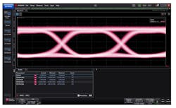
To measure TDFOM, you would use the same test setup as other Tx test parameters, such as OMA, relative intensity noise (RIN), extinction ration (ER), and jitter (Fig. 5). And the SSPR-NRZ or SSPR-PAM4 test patterns would be utilized (Fig. 6).
The input low-pass filter of the TDFOM reference receiver is the 4th order Bessel-Thomson filter with BW-3dB = 16.4 GHz for all data rates. The TDFOM also employs a reference receiver with specific timing recovery, additional signal filtering, and decision feedback equalizer in the signal path.
The oscilloscope should be set up to capture samples from all symbols in the complete test pattern, averaging a number of samples per unit interval (UI) larger than 15. The optical splitter and variable reflector are adjusted so that the transmitter is tested with the optical return loss as specified in the IEEE 802.3cz PMD transmitter characteristics, which is 12 dB max.
For Tx conformance tests, the oscilloscope should provide the measurements required to perform the test parameters, including TDFOM and others. The good news is that many of the Tx measurements can be leveraged from existing measurement functions used for datacom optical transmitter test.
IEEE 802.3cz PMD Rx Conformance Test
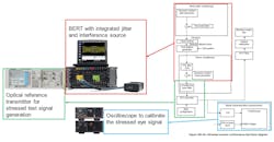
For the Rx test, stressed receiver sensitivity measurement is used to validate the receiver PHY’s ability to detect a degraded or stressed signal over the fiber. This ensures that it will work well in the noisy and inherently harsh vehicle environment. Testing the receiver can be more complex and requires more testing methods than testing transmitter. Figure 7 shows the block diagram of the 802.3cz optical receiver stress test.
The key instrument to note here is the BERT. It combines the pattern generator and the error detector. It generates electrical test patterns with or without stressed pattern. The optical reference transmitter converts it into an optical format and allows for feeding to the DUT receiver.
The BER is calculated by picking up the error counter register values in the BER test mode and comparing the number of bits transmitted. You will need a side-band communication to reset the error counter and fetch the error-counter values. The oscilloscope in the diagram calibrates the test signal level to ensure the stressed test pattern has the right amplitude and signal conditioning according to the 802.3cz TDFOM, RIN, and jitter test requirement.
Three test parameters are required to perform the 802.3cz-compliant receiver characteristics of the optical PHY: stressed receiver conformance test signal calibration (STDFOM and ER), stressed receiver conformance test signal calibration (RIN and random jitter), and stressed receiver sensitivity.
Stressed receiver sensitivity is a test that measures the ability of a receiver to detect a degraded signal over the fiber. The signal is degraded by stressed signal conditioning, such as jitter to the signal. The stressed receiver sensitivity is defined in specific OMA values in dBm over STDFOM for each PHY type.
Conclusion: The Impact of Glass Optical Fiber on Automotive Networking
As the automotive in-vehicle-networking requirement approaches the 100 Gb/s*m speed-length threshold, the need to move away from copper and toward optical communication links has become a reality. Automotive applications have evolved and can now derive significant benefits from glass optical fiber technologies.
Glass-optical-fiber-based automotive Ethernet will be a critical enabler for next-generation vehicles, supporting EMI/EMC proof interface, higher data rates with excellent signal integrity, low cable harness weight, etc. Other product solutions enabling multi-gigabit optical automotive Ethernet, including components (cables, connectors, optical transceivers) and test and measurement systems, are coming to market now.
In this article, we overviewed the physical-layer test systems and test requirements as outlined in the IEEE 802.3cz multi-gigabit optical automotive Ethernet. We also examined the test equipment and configurations needed to perform the optical transmitter and receiver conformance test, as well as the key test parameters and measurement methods to perform the test.
One very important measurement parameter highlighted in the article that was added to the IEEE 802.3cz standard is TDFOM or “Transmitter Distortion Figure of Merit.” It’s a main metric used to measure the quality of the optical signal transmitted over a fiber-optic cable and to guarantee interoperability of transmitters in terms of signal integrity valid to be received by a compliant receiver.

