This article is part of the TechXchange: EV Battery Management.
Members can download this article in PDF format.
What you'll learn:
- The growing demand for efficient battery testers.
- How to calculate ac power requirements.
- Calculating ac power per phase for a three-phase system.
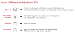
One major factor driving the lithium-ion battery industry’s rapid growth is adoption of electric vehicles (EVs) into the mainstream market. While EVs represent less than 5% of the cars on the road today, environmental concerns, global warming, government mandates, consumer preference, oil supply, and gas prices are driving automakers to accelerate their plans to bring EVs to market. Figure 1 illustrates the impact of EV adoption.
1. Cell and battery makers will feel the impact of EV adoption going mainstream, creating new needs and challenges.
Hence, as EVs go mainstream, cell and battery makers will face the following challenges that impact their design, test, and validation equipment:
- Utilize and test higher-voltage batteries in EVs for efficiency.
- Grow the number of test systems operating in their lab.
- Manage huge volumes of data to achieve insight.
- Use energy efficiently during energy-intensive testing.
Testing is Energy-Intensive
Using more testers to perform added parallel testing will be required to drive accelerated design cycles. Furthermore, as cell capacities increase and battery packs grow in size to address increased range, the amount of energy used during each test will ramp up. Some tests, like lifecycle testing, consume a large amount of total energy due to the long duration of the tests, which could proceed for weeks and months.
Energy-Efficient Equipment for Reducing Energy Costs
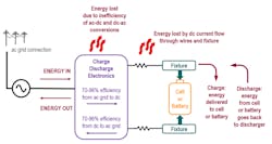
To keep laboratory operational expenses down, engineers will seek energy-efficient equipment. Figure 2 shows the energy flow, efficiency, and losses during cell charging and discharging. It presents a first step toward understanding how to determine total ac power requirements during test laboratory operation.
2. Shown are the energy flow, efficiency, and losses during cell charging and discharging.
During charging, ac power is delivered from the ac line, through the ac-dc power-conversion stages, through wiring and contacting, into the cells or batteries. During discharging, the energy stored in the cells or batteries flows through wiring and contacting, back into the test equipment.
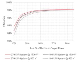
The ac-dc power-conversion efficiency during charge can range from 70% to 96%. During discharge, the efficiency can be 0% or 70% to 96%, depending on the equipment. However, these stated efficiencies are for a specific operating point where the conversion efficiency is at its maximum. Efficiencies drop because the operating point is at a low percent of the full-scale output power. At very low current and/or very low voltage, the efficiency can be quite low (Fig. 3).
3. The graph illustrates system power efficiency vs output power for Keysight SL1700 Battery Test System (see image at the top of the article), which uses silicon-carbide technology to achieve high conversion efficiency. For more info on this system, click here.
Another consideration is the power loss in the wires and contacting to the cell or battery. This power will be lost as heat, so it’s important to keep wire size large, resulting in low wire resistance, as well as keeping contact resistance low. Even while keeping losses to a minimum, you must account for these losses when calculating laboratory power requirements.
During discharge, once the power reaches the equipment, two energy-management strategies can be employed. One strategy typically used in lower-power and lower-cost equipment is simply to dissipate the power as heat inside of a heatsink. In this case, the efficiency of discharging is 0%, because 100% of the energy is lost as heat in the test equipment.
The second strategy is to utilize regeneration. The regenerative discharger will convert the power coming from the cell or battery to ac power. Regenerative discharger circuits will normally achieve somewhere between 70% to 96% dc-ac conversion efficiency. For more information about regeneration, check out the article “Reap the Benefits of Regeneration When Testing or Forming Li-Ion Cells.”
Calculating AC Power Requirements for Testing
Whether the test equipment is highly efficient with regeneration or less efficient utilizing dissipation, you will need to understand how much power the equipment consumes to determine the ac power requirements of your testing laboratory.
As a start, determine the maximum power required by your device (cell or battery). The maximum power could be during charge or discharge. If the equipment is regenerative, use the larger of the charge power or discharge power to determine maximum ac requirements. If the equipment isn’t regenerative, the maximum power is present during charge since the discharging has no ac power impact.
Figure 2 describes wire and contacting losses. At this point in your calculation, add in the power lost in the wiring and contacting. The result will be the maximum power needed, including the power required to charge or discharge the cell or battery plus the losses during charge or discharge. This will give you the maximum total dc power per device.
Next, multiply the maximum total dc power times the number of devices being tested. For cell testing, it’s possible many cells will be tested in parallel, and the total power can quickly grow large.
When regeneration is available, some might argue by balancing the charging and discharging within the cells or batteries, you can reduce total power consumption and thereby reduce ac line power requirements. It’s true the energy regenerated from discharging will offset some of the energy needed by charging, resulting in a net lower ac power demand.
However, in certain scenarios, all devices are charging or discharging. For example, when the test system is first turned on, perhaps all of the devices need their initial charge, so you must size the ac power to match this “all charging” worst case. For more information about balancing, see “Balancing Power Usage During Battery-Cell Test."
Now that you have the total dc power required, including losses in the wires, you must consider the ac power-conversion efficiency. From the equipment manufacturer, you will need to obtain the efficiency percentage at the power required by your test. Then, to calculate required ac power, use: total ac power = total dc power / efficiency %.
Let’s say the equipment efficiency is 85% and you need a total of 50 kW of dc power to test the cells or batteries. This would result in 50 kW / 85% = 58.8 kW of total ac power.
Three-Phase Systems
Small systems requiring a few kilowatts of total power can easily run from a single ac phase, but most cell or battery test systems will require much more power than what’s available with a single ac phase. Therefore, you’ll need to determine the ac line current per phase for a three-phase system.
To begin, determine ac power per phase by this calculation: ac power per phase = total ac power / 3. So, for this example of 58.8 kW total, that would be 58.8 / 3 = 19.6 kW per phase.
Typically, a three-phase ac power system is specified by line-to-line voltage. For instance, in Europe, industrial ac power is 400 V ac line-to-line. In the U.S., industrial ac power can be 208 V ac line-to-line or 480 V ac line-to-line.
For this calculation, since we’re trying to determine ac current per phase, we need to know line-to-neutral voltages. In a three-phase ac power system, to convert line-to-line ac voltage to line-to-neutral ac voltage, use this calculation: line-to-line ac voltage / √3. If you have 400 V ac line-to-line, you have 400 / √3 = 400/1.732 = 230 V ac line-to-neutral.
Now you can calculate ac current per phase: ac current per phase = ac power per phase / ac line-to-neutral voltage. Again, for this example, 19,600 W ac per phase / 230 V ac line-to-neutral = 85 A ac per phase for a 400 V ac line-to-line ac system.
Finally, you may want to consider adding some margin on these calculations. The ac power grid can vary the ac line voltage amplitude (in volts peak-peak) by ±10%. When the line voltage drops by 10%, to provide the same power, the line current will go up by 10%. Therefore, when specifying the ac current input, you should consider adding some margin. I recommend 10% to 20% margin.
Summary
Expanding power requirements for testing drive the need for efficient equipment, but even efficient equipment can require high power from the ac grid. Understanding how to calculate power is key to ensure you don’t overtax the ac power lines into the test laboratory.
Read more articles in the TechXchange: EV Battery Management.


