What you’ll learn:
- Why a conventional thermal fuse may not be adequate for EV/HEV battery-related safety.
- How using a pyro fuse offers a fast-acting, programmable alternative.
- Operational and safety issues when using an IC to trigger the pyro fuse.
There’s no doubt that the large battery packs in electric and hybrid vehicles (EV/HEVs) need some sort of super-quick electrical cutoff from the rest of the vehicle wiring and chassis in case of emergency, accident, or some types of internal failures.
The first solution is obvious: Get a properly sized, classic thermal fuse with the suitable response characteristics. These melting fuses trigger the cutoff based on thermal conditions resulting from an overcurrent event and are preset to activate at a fixed value determined by their design and fabrication. (Note that there’s nothing simple about “simple” automotive fuses.1)
Using a Pyro Fuse for Quick Cutoff
But that capability may not be sufficient for the battery-management systems (BMS) of EV/HEVs. For truly quick and total cutoff, and independent of the magnitude of the current flow, there’s the option of a “squib” or pyro fuse, a miniature explosive device that cuts off the current in about a millisecond.
(Note that squibs aren’t new or unique to autos, as they’re widely used in many critical situations as well as in automotive airbags. Further, while resistor dissipation and thermal rise are generally undesirable I2R consequences of their function, squibs use a design and configuration called an electro-pyrotechnic ignitor chip resistor specifically designed for fast self-heating and associated dissipation.)
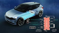
The challenge is to drive the squib to activate, and under different scenarios. That’s the role of ICs such as Texas Instruments’ DRV3901-Q1 single-channel squib driver for automotive EV pyro fuses (Fig. 1).
This IC not only provides the needed squib drive when instructed to do so by an MCU, but also includes many other features and functions for reliability and safety. It can be directed by an addressable SPI bus (to support multiple ICs). However, this, of course, adds several layers of intermediate complexity between triggering event and action triggering.
For this reason, its deployment command can also be issued directly via hardware to enable the flexibility to trigger via MCU hardware pins, directly with an overcurrent sensor, or through other external hardware-based sensors and circuit monitors.
Monitoring the Driver’s Health
Furthermore, the built-in diagnostics monitor tracks the various aspects of the driver status, pyro-fuse health (via squib resistance), and backup power availability. A capacitor acts as a backup power source for the pyro-fuse system for situations where the main supply from the battery is no longer available.
In turn, this backup supply needs monitoring, so the reservoir capacitor is measured by periodically checking the discharge voltage of the capacitor. This enables the DRV3901-Q1 driver and the MCU to detect a failure of this backup power supply before its needed and subsequently alert the vehicle (hello, “check engine” light!).
The configurable deployment current/pulse widths of this device are 1.2 A for 2 ms, through 1.75 A/0.5 ms, up to 3.4 A/0.5 ms. Housed in a compact HVSSOP-28 (DGQ) leaded package, this functionally safety-compliant IC can function with up to 28-V operating voltage (40 V maximum) and is AEC-Q100 qualified for automotive applications (temperature grade 1: –40 to +125°C).
It’s supported by a 16-page datasheet and documentation is available to aid ISO26262 system design up to ASIL C level. There’s also a short but interesting technical article with representative waveforms and timing.2
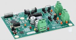
For those who want to further explore the DRV3901-Q1, TI offers the DRV3901-Q1EVM evaluation module (Fig. 2). This module supports the use of two DRV3901-Q1 devices for flexibility in testing parallel or redundant systems.
For those interested in learning more about pyro fuses, TI cites one example: the PSS-4 Battery Disconnection Switch from Autoliv (Fig. 3).
This device operates in under 1 ms, handling a maximum continuous current of 350 A at 105°C at up to 600 V DC (and 25 kA peak current-carrying ability). Not including contacts, the body measures about 42 mm2 and 70 mm deep, and the device requires 0.75 A /0.5 ms for initiation.
References
1. Bourns (via Electronic Design), “Increase Reliability in Harsh Environment Apps with Automotive-Grade Fuses.”
2. Texas Instruments, SSZTCU8, “How squib and contactor drivers help improve safety and efficiency in HEV/EV battery disconnect systems.”


