What you’ll learn:
- Op amps played a critical role in knocking out German cruise missiles in WWII.
- Scientists at Bell Labs came up with a spiffy, high-gain, differencing amplifier.
- Andy’s still threatening to run SPICE simulations.
Balanced or diff amp?
Mad scientists built a gun.
K2-W's first stage!
Yup. As I had threatened to do in Part 1, we’re eventually going to take a shot at simulating the K2-W Analog Computer Op Amp in SPICE to gain some insight on its first stage’s operation and characteristics. Hardcore analog designers would rather fight than switch, and there’s really no substitute for building prototype circuits and test chips on the bench. But the reality is that we would not have a single analog or mixed-signal integrated circuit or integrated op amp without SPICE models and SPICE simulations.
SPICE also gives us a very quick (usually!) set of “what if’s,” validates design theory and intuition, and gets us adequately close on a first design iteration before we prototype or tape out a chip—if you can get it to converge. If I haven’t succeeded in persuading you that you won’t be haunted by The Ghost of Bob Pease for doing SPICE simulations, there’s no hope and you can read the rest of this like you would a comic book.
Becoming SPICEy
So, the first step in all of this “SPICE simulation stuff anyhow” is to find a decent model for the vacuum tubes for the K2-W's 1952 op-amp design. Fortunately, audio snobs love to play with vacuum-tube design for (pre-)amplifiers, and we can pilfer a fairly decent LTspice model of the 12AX7 dual triode1 from them here.
Some might call me “lazy,” but I like to call it “being efficient with my time.” I simply took the tube-boffins’ audio amp schematic and deleted everything but the 12AX7 tube and the SPICE directives. Then I built up a K2-W first stage schematic (ignore right half of the drawing for now—I’m trying to save page space here) that’s comprised of two triodes, both of which are in one dual triode 12AX7 (see figure).
On the left half of my LTSPICE capture of the K2-W’s input stage schematic, the two cathodes are connected, which should be familiar for a “differential” pair. In place of the classical current source we’re used to seeing, there’s a “long tail” 220-kΩ resistor that’s connected to a pretty high voltage… −300 V DC. As you can see, there’s some Voodoo in play here already, as compared to the classic diff-pair amplifier circuits from our textbooks.
The anode (plate) of the first triode’s plate (anode) is directly connected (more Voodoo) to the +300-V DC power supply, while the second triode’s plate is connected to +300 V DC via a 220-kΩ load resistor. Also included in my schematic is the K2-W’s level shifter... 1- and 2.2-MΩ resistors running between the second triode’s load resistor and the −300-V DC supply. We’ll be looking at the node between these two resistors as “Vout.”
Getting Your Gedankenexperiment On
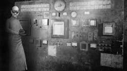
Before we run the simulator, let’s first toast some brain cells with a Gedankenexperiment: What’s going on with that first load resistor being missing? In Walt Jung’s Op Amp book’s history chapter, Figure H-4 (sorry, it’s copyrighted so you’ll need to click here and go to page H.19 to see it), we see the very same missing load resistor in a cathode-coupled input pair, and cathode resistor(s), as used in the M9 Gun Director (takes newfangled-radar inputs and aims/fires the antiaircraft gun using an analog computer) single-input op amp designed by Bell Labs for successful use by Allies in the Second World War. Missing load resistor? What the…?
After some eye rubbing, we can see that the first triode in my LTSPICE schematic is really nothing more than a cathode- (“source-” for the FET analogy folks) follower circuit. But Bob and Walt said the K2-W has a differential, or “balanced,” input. There’s nothing balanced about a cathode follower, is there? OK, now it’s time to tie yet another knot in your now-pretzeled brain…
Look carefully at that second triode circuit. Though I’ve pinned its control grid to ground for my simulations, it’s a second voltage input in the K2-W’s case—the K2-W op amp’s positive input. Let’s say, for analysis purposes, it’s a fixed voltage. In my case, it’s 0 V. Hmmm…load resistor on the anode (plate, or drain if you want to think of it as a FET), fixed voltage on the control grid (gate on your FET), and you get….a cascode amplifier’s upper stage.
So, if we bounce the coupled cathodes’ resistor voltage up and down with the voltage follower, that cascode will AMPLIFY current in the cascode’s load resistor, creating voltage gain. Since the first triode voltage-follower input follows the negative input, and the second triode’s cascode input moves the output in the opposite direction of its control grid (relative to its cathode), we get SUBTRACTION or a DIFFERENCING of the positive and negative voltage inputs with the bonus of voltage gain.
Off Balance
So, what the K2-W has for an input stage is not “balanced” by any sense of the imagination (Pease even dismisses it as “built-in offset in one direction”), nor is it a differential circuit in the classical sense where we get some nice common-mode rejection. Can’t really get that when your plate is connected directly to the positive power supply on one side and the supply goes through a load resistor on the other plate.
Voodoo....that saves a resistor? Yes, but that’s not why they did it and the easiest way to show what’s going on is to *gasp* run LTspice. I keep promising to do so and in our final part of this three-part series (I have a word count limit), on TUESDAY of next week’s blog, we’ll really do it.
As a reminder, I normally post a blog the first and third Monday of the month and I’ve decided to make this little word-count blowout an exception. I’ve got some goodies coming in that will have us doing some benchwork soon enough, so please be patient if you’re in the rat’s-nest-breadboarding camp.
Reference
1. Before the younger generation gets scared off with this Boomer tube stuff, a vacuum-tube triode operates pretty much the same as a depletion-mode FET (MOSFET/MESFET/etc.). Instead of a channel of current being modulated by a gate voltage, a vacuum tube boils off electrons (yes, real electrons) from a cathode using an incandescent heater, and because of the voltage between the negative cathode and the positive anode, the electrons are accelerated (unlike charge attracts) to the plate (anode). Yes, kids, electrons flow from minus to plus despite “conventional current” flowing from plus to minus—this is one reason why old tube-people seem very confused. The triode inserts a “control grid” into what was a “diode,” a physical screen like the one on your mom’s back porch door, between the cathode and anode. By making that control grid more negative in voltage, fewer electrons can get through to the anode. A small change in control grid voltage effects a large change in current between the cathode and anode, and an amplifier is born. So, think of a triode tube as a very-high-voltage FET that gets progressively shut off (Brits call them “Valves”) with more negative voltage and you’re good.
