What you’ll learn
- The need for single-use, low-capacity batteries.
- How paper infused with simple solution and “printed” contacts can form a basic battery.
- The results achieved with this battery design and implementation.
Battery research predominantly focuses on performance, constantly working toward higher energy and power densities, faster charging rates, and improved operation stability. Correspondingly, there’s limited research on biodegradable primary batteries as a complementary and versatile source of energy
However, as noted by a team at the highly respected Swiss Federal Laboratories for Materials Science and Technology, known as EMPA (the German acronym for Eidgenössische Materialprüfungs und Forschungsanstalt), a large set of applications need only a modest amount of power and become one-shot applications. These include single-use electronics for point-of-care diagnostic devices, smart packaging, and environmental sensing.
Even if slimmed down, the cost and environmental impact of using conventional battery structures can still be significant. Addressing this situation, EMPA researchers devised a disposable paper battery that reduces the environmental impact of batteries in such single-use applications. Their basic battery, approximately 1 cm2, uses zinc as a biodegradable metal anode, graphite as a non-toxic cathode material, and paper as a biodegradable substrate.
The battery remains inactive and thus retains its full energy capacity until water is added and absorbed by the paper substrate, taking advantage of its natural wicking behavior. Once activated, a single cell provides an open-circuit potential (OCP) of 1.2 V and a peak power density of 150 µW/cm2 at 0.5 mA.
Materials and Inks
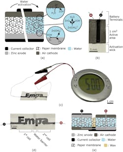
The materials are both simple at first glance yet sophisticated (Fig 1). The anode and cathode materials they developed are compatible with additive manufacturing techniques and can be stencil printed in a wide range of shapes and sizes. The paper, which serves as a separator between the anode and cathode, is infused with the dry electrolyte that requires only a few drops of water to be activated.
1. (a) Illustration of the water-activated paper battery. Its electrochemical (EC) cell consists of a paper membrane sandwiched between a zinc-based cathode and a graphite-based air cathode. Carbon-based current collectors are used to extract charges from the EC cell and contact with external circuitry. The device remains inactive until water, which serves as the electrolyte, is provided to the system and permeates the paper membrane. (b) Picture of single-cell battery fabricated by stencil printing on filter paper. The device is activated by immersing the wick in water or any aqueous solution. At the battery terminals, the filter paper is impregnated with wax to avoid electrochemical reactions of the lead wires and to provide mechanical stability. (c) Photograph of a stencil-printed paper battery with a design that spells the name of the research institution (Empa). The battery can run low-power electronics such as the LCD alarm clock shown in this photograph. The device is composed of two electrochemical cells that are separated by a water barrier as depicted in the (d) photograph, and connected in series as illustrated in the (e) schematic cross-section of the battery with its overlaid equivalent circuit (for ideal voltage sources).
The battery consists of three inks printed onto a rectangular strip of paper. Standard salt (sodium chloride) is dispersed throughout the strip of paper and one of its shorter ends is dipped in wax. An ink containing graphite flakes and functioning as the positive end of the battery (the cathode) is printed onto one of the flat sides of the paper, while an ink containing zinc powder is printed onto the reverse side of the paper as the negative end of the battery (the anode).
Another ink that contains graphite flakes and carbon black is printed on both sides of the paper, on top of the other two inks. This ink makes up the current collectors connecting the positive and negative ends of the battery to two wires, which are located at the wax-dipped end of the paper. The role of the current collector is to connect the cathode and anode to external circuitry.
All of the inks were specially developed and tested to ensure that they exhibited shear-thinning gel properties that were compatible with additive manufacturing techniques such as stencil printing and extrusion-based 3D printing.
When a small amount of water is added, the salts within the paper dissolve and charged ions are released, thus making the electrolyte ionically conductive. These ions activate the battery by dispersing through the paper, resulting in zinc in the ink at the anode being oxidized, thereby releasing electrons.
By closing an external circuit, these electrons are transferred from the zinc-containing anode—via the graphite- and carbon black-containing ink, the wires, and the device—to the graphite cathode where they are transferred to, and hence reduce, oxygen from ambient air. These redox reactions (reduction and oxidation) thus generate an electrical current that can be used to power an external electrical device.
Tests and Results
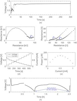
Analysis of the performance of a one-cell battery showed that when just two drops of water were added, the battery activated within 20 seconds (Fig. 2). After one hour, the one-cell battery’s performance decreased significantly due to the paper drying.
2. (a) Graph of the open circuit potential (OCP) of the single-cell battery as a function of time upon activation. Time zero corresponds to the moment water was dispensed on the activation wick. The battery shows a stable 1.2-V OCP and a 20-second activation time. (b) Nyquist plot of the battery before activation, showing an internal resistance Rint of 85 kΩ. (c) Nyquist plots of the battery immediately upon activation (gray squares) and after one hour of discharge at 100 μA (black dots), showing internal resistances Rint of around 70 Ω and 90 Ω, respectively. (d) Chronopotentiogram of the battery (black solid line) and the corresponding current ramp (gray dotted line) as a function of time. (e) Graph of the power generated by the battery as a function of the current, showing a maximum of 150 μW at 0.5 mA. (f) Chronopotentiogram of the battery at a constant current of 100 μA, showing the process of drying and reactivating the device. The discontinuity in the data points is due to complementary analysis that was carried out on the sample at its peak operating voltage.
However, after the researchers added two extra drops of water, the battery maintained a stable operating voltage of 0.5 V for more than one additional hour. As a demonstration, the team combined two cells into one battery to increase the operating voltage and used it to power an LCD alarm clock.
"What's special about our new battery is that, in contrast to many metal air batteries using a metal foil that is gradually consumed as the battery is depleted, our design needs to add only the amount of zinc to the ink that is actually needed for the specific application," said project leader Gustav Nyström.
The work is detailed in their readable paper “Water activated disposable paper battery” published in Nature. There’s also a two-page Supplementary Information posting with graphical top, bottom, and side views of the single-cell battery fabrication process at each step.


