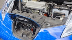
This article is in TechXchange: Why Low Iq is the Smart Thing to Do
Members can download this article in PDF format.
What you'll learn:
- What is the quiescent-current control module?
- How to do a parasitic draw diagnostic.
In the automotive market, a multitude of buck-converter ICs enable automotive power engineers to achieve low quiescent current. This effort will help extend battery runtime, especially in applications like infotainment systems that will require standby-mode power coupled with a compact solution. Buck converters also enable a reduced external component count, reducing system cost.
The complete system consists of three components:
- Battery-management-system (BMS) control module (see TI HEV/EV BMS).
- Great Wall Motor (GWM) technology.
- Quiescent-current control module (QCCM): There’s a patent for a vehicle quiescent-current control method, system, device, and computer readable storage medium, and another patent for a control device for quiescent current of automobiles.
Many of the latest high-performance vehicles, such as Jaguar/Land Rover and others, have a QCCM.
The QCCM
The quiescent-current control module is located at the right rear corner of the luggage compartment in a Jaguar. Most other vehicles with a QCCM will have a similar location within the vehicle. The QCCM will cut power supplies to other non-essential control modules to prevent an excessive discharge of the primary battery.
The QCCM is in addition to the BMS and uses signals already transmitted by the BMS control module(s). The systems supplied via the QCCM are usually the audio/entertainment systems and the climate-control systems. The software that controls the QCCM is contained within the GWM.
In some cases, the control modules may cause an unnecessary battery drain due to the module staying awake after the vehicle electrical system has shut down. The QCCM, in conjunction with the GWM, monitor and control the vehicle systems to prevent any battery drain.
The BMS will proceed to check the primary battery health by analyzing battery quiescent current, battery current drain, or state-of-charge, and decide if any action is required to protect the primary battery. If action is required, this will be communicated to the GWM control logic, which will use this information to assist primary battery protection. The QCCM receives open and close commands from the GWM and will react accordingly.
Upon vehicle delivery, the system will be set in transit mode. Transit mode has no QCCM operation and the relays will remain closed; thus, the battery drain may occur and the system will not react to it. A pre-delivery inspection (PDI) process requires that the system be placed in the Normal mode, which enables the QCCM, before handing the vehicle over to the customer.
The QCCM has another function—a routine to clean the relay contacts if necessary. This routine is performed via a Land Rover-approved diagnostic system. If a problem is detected, the unit will require replacement.
The QCCM also contains several fuses that will supply and protect the audio/entertainment systems, as well as the climate systems.
Using a Parasitic Battery Drain Diagnostic Even in Intermittent Situations
A parasitic drain on a battery can be usually simple to diagnose and locate. Typically, some device has been left on and is draining the battery down. Troubleshooting requires measuring the voltage drop across the fuses, which can help locate the problem circuit. Murphy’s Law could arise when it becomes challenging to locate the current drain, especially when the draw is an intermittent problem.
Running a parasitic draw diagnostic on the vehicle in a 24-hour period will require a Power Probe Hook (also known as the Supply Hook), which can measure the amperage without the unit entering a sleep mode. The first step is parking the vehicle in a bay where it would not be moved. Then set up the proper tools to check for the current draw.
Occasionally measure the vehicle for any rogue current draw and hopefully we will see a current draw. For example, if the Hook shows 8.79 A,1 now the fun starts as we try to isolate the circuit causing the current draw. (There was a previous experience in another vehicle where the battery control module, or BCM, woke up and drained the battery due to a defective door switch)
First, using an oscilloscope or multimeter (with a fresh battery), measure and record the voltage drop across all fuses. Then use a multimeter or oscilloscope to measure the voltage drop across each fuse in the BCM. The BCM fuse showed a voltage drop on the scope along with the amperage draw on the Hook.1 Something was triggering the BCM to wake up.
Now we will need to isolate the other network modules or computers to see which of the modules was triggering the signal to the BCM. With the bus bar still disconnected, a jumper was installed from the BCM computer network terminal to each of the other computers (one at a time) on the network.1
Technicians found that the driver’s door module was activating the BCM. Success!
Summary
In this article, we emphasized the latest quiescent-current control in automotive vehicles. The QCCM is at the heart of motor vehicle electronics, helping to minimize discharge of the main automobile battery. An optimum BMS will monitor primary battery health by analyzing the battery quiescent current and any unnecessary current drain on the battery. It’s then able to decide if any action is necessary to protect the primary battery. If action is required, the QCCM can communicate the battery system status to the GWM.
Read more articles in TechXchange: Why Low Iq is the Smart Thing to Do
References
1. Diagnosing an Intermittent Parasitic Draw
2. Jaguar battery care manual: Vehicle quiescent current testing
