With each electric car that is sold today, economic performance and driving range only increase in importance. Squeezing every last joule of energy out of the batteries and the electrical system is mission critical to design engineers. Development of series production-ready high energy per volume solid-state batteries is being pushed by many OEM and Tier 1 suppliers.
During vehicle development, engineers perform energy flow analysis in order to understand energy transfer efficiency and the proportion of energy consumption among various subsystems. This analysis informs the economic performance analysis simulation model, guiding the formulation of reasonable performance indicators. Precise measurement and prediction of vehicle energy consumption are needed for both development and vehicle operation. Development of efficient and EMC emissionless electric components like e-motors, inverters, chargers, and power management systems is in full swing.
Outside the vehicle, intelligent Vehicle-to-Grid energy management, wires for fast and high-power energy flow, and inductive charging solutions are under development. The technology to support these mega-trends is well past the “wish list” stage. As a result, recent electric vehicle developments show a need for current sensors with accuracy classes from 0.1% to 0.01% for accurate power measurements, with short-term peak currents up to 2000 A.
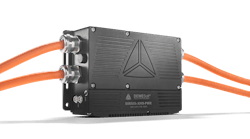
To support the development of today’s and tomorrow’s electric vehicles, data acquisition developer Dewesoft has developed the SIRIUS XHS-PWR high current and high voltage measurement system. Achieving the combination of high bandwidth and extreme voltage and current measurement accuracy required for these tests, in a small and rugged form factor suitable for the testing environment, were the major technical challenges involved in creating the SIRIUS XHS-PWR.
Core Technologies
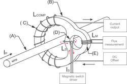
For example, the SIRIUS XHS-PWR electric vehicle data acquisition system is based on several advanced core technologies, most notably of which is the DC-CT current sensing transducer. This approach achieves extremely accurate current measurements in the most demanding applications, including measuring very high current peaks and leakage current. The DC-CT current measurement transducer system is built on a single high-permeability core and a zero-flux closed-loop null method measurement principle, with the innovative Platiše Flux Sensor (PFS)(Figure 1).
The DC-CT transducer can be seen as an AC current transformer (CT), where primary and secondary windings couple the transformer for AC signals, down to a few Hertz. Just as with other closed-loop technologies, the PFS continuously measures residual magnetic flux in the core resulting from the difference between the primary and secondary (compensation) currents. The output from the PFS is proportional to the magnetic flux in the core. It drives feedback control circuitry to adjust the compensation current to restore the optimal zero-flux balance in the core. Therefore the compensation current accurately mirrors the primary current, scaled by the number of primary versus secondary turns.
DC-CT technology with the Platiše Flux Sensor represents the latest current sensing technology with ranges of 100, 500, and 1000 Amps, >500 kHz bandwidth, and high performance. Excellent linearity, precision, accuracy, immunity to external magnetic fields, low offsets, and extremely low-temperature drift are achieved at low power operation. It can also directly measure voltage up to 2000 V peak (with CAT II 1000 V safety), with up to 5 MHz bandwidth.
DC-CT technology uses an innovative principle of isolated measurement of DC and AC currents. Within a magnetic core, magnetic flux can only be measured if it is non-constant ( i.e., changing or alternating). Since a DC current generates a constant magnetic flux, the innovative principle redistributes this flux among two or more paths periodically in a single core. If we observe this magnetic flux from one path only it appears alternating and is therefore easily measured by a simple winding whose voltage is proportional to the measuring current.
This has been achieved by the invention of a current-controlled variable reluctance circuit. This vital component is composed of an “infinity winding” embedded into a gap-less core that retains the good properties of high permeability materials. Comparing this principle to widely used Hall-effect based sensors inserted into a magnetic core, the DC-CT solution does not create any air-gap, retaining very high sensitivity and immunity to external magnetic fields. In addition, the new DC-CT sensing principle is temperature independent.
Let’s compare this principle to the most widely used high-end flux-gate transducers, in which a flux-gate adds energy to the core to alternate the flux between the maximum and minimum operational limits of the core, consuming a significant amount of energy. The value of the current can be extracted from the second harmonics, the pulse-width-modulation in self-oscillating solutions, or other methods (Table 1).
High-end flux-gate solutions require up to three cores instead of just one, as in the case of the DC-CT current transducer. Two of them are required for sensing, operating in opposing directions to reduce injected noise, and the third is used to extend the AC bandwidth. Flux-gate sensors reset the core repeatedly, while the DC-CT demagnetizes the core upon request. DC-CT is therefore energy-efficient, compact in size, low noise, high bandwidth, temperature independent, and cost-effective. Existing products are available from 2 A up to 2000 A, with up to 1 MHz bandwidth and target accuracy from 0.1% down to 0.01%.
Other potential uses include to replace DC/AC residual current sensors of class B+. Looking closer at the Platiše Flux Sensor, its conceptual design is based on a magnetic core (B) through whose center runs a wire carrying the current to be measured, also named the primary current Ip (A). The secondary compensation winding (C) Lcomp contains a greater number of turns and is distributed around the majority of the magnetic core. Magnetic material then introduces additional openings, to form a Platiše Flux Sensor (PFS). The PFS is composed of a current-controlled variable reluctance (CCVR) and the Ls winding (D) on the left side of the opening, and flux measuring winding Lm (E) on the right side of the opening.
The difference between primary and secondary currents creates a residual or non-compensated flux in the core, and without the presence of the current in the Ls winding, the CCVR portion redistributes quasi equally among the paths (D) and (E). Stimulating the Ls winding (D) with electric current lowers the permeability and thus increases the resistance of path (D). It acts as a kind of a magnetic switch which, with the presence of current, quasi opens; and then the flux which was before distributed quasi equally among the (D) and (E) paths is forced to flow mainly through (E). In the PFS measurement cycle, the Ls winding is continuously switching and chops the residual non-compensated magnetic flux, and continuously redistributes the flux between (D, E) paths and (E) only.
To simplify, let us say that in the first step each path sees half of the flux, and in the second step the entire flux flows through (E) only, and none through (D). Therefore such a huge flux change dΦ/dt through the (E) path is easily captured by the Lm winding. The rectified (demodulated) output magnitude is directly proportional to the magnitude of the residual magnetic flux, and its phase is proportional to the sign of the flux.
HybridADC Analog-to-Digital System
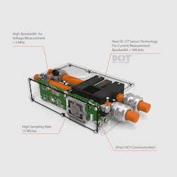
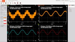
Another important core technology within the SIRIUS XHS-PWR is the HybridADC data acquisition system. After all, there is no point in putting a high bandwidth sensor into a DAQ system that lacks the bandwidth to handle it. One of two recording modes can be selected for each channel independently, according to the application. There is a High Bandwidth Mode, with more than 5 MHz bandwidth and up to 15 MS/s sampling rate. The SIRIUS XHS-PWR can acquire impulse, step, and square signals without any ringing or overshoot. This mode is perfect for transient recording and power analysis, and uses low-latency SAR ADC technology. There is also a High Dynamic Mode with a sample rate up to 2 MS/s, that can be selected with 24-bit resolution and brick-wall anti-aliasing filtering, meaning that frequencies above the passband are fully rejected. In this mode, SIRIUS XHS-PWR operates with Sigma-Delta ADC technology (Figure 2).
It is important to note that each of the channels can be set to either of these modes: some can be high bandwidth and some can be high dynamic, and all signals are perfectly time-aligned with each other with zero phase shift. Data can be synchronized with other data sources, such as vehicle bus interfaces like CAN (and others), as well as GPS, IMU, video, and more. SIRIUS XHS-PWR instruments can be synchronized using the PTPv2 protocol, IRIG time code, or a PPS signal. Absolute time synchronization can also be achieved using in-house time servers or GPS.
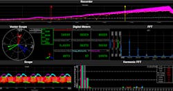
DewesoftX software automatically calculates and stores not only the raw data from the voltage and current transducers, but also all of the power parameters, like P, Q, S, D, Cos φ, power factor, as well as P, Q, cos φ for each harmonic, and more. Each parameter can be displayed visually in a variety of time history graphs, FFT graphs, scopes and numeric displays. Power-centric displays like Vector Scope and Harmonic FFT are also included and can be placed anywhere on the screen. Using a computer graphics card as a multi-threaded calculation platform, the DewesoftX power module can calculate all of these parameters up to the top sample rate of 15 MS/sec (Figure 3).
Compatibility with Standard Protocols
In today’s world of open tool chain and intercommunication, devices should be compliant with standard protocols. All of these protocols can be used simultaneously with SIRIUS XHS-PWR. OPC UA is more than just an industry standard protocol, OPC UA is a solid framework where the SIRIUS XHS-PWR can be described and set up in any system, including SCADA, MES, ERP, mobile devices, and others.
XCP on Ethernet (TCP/IP) started with version 1.4, XCP, and became a very powerful interface protocol for data exchange in the automotive industry. In this age of e-mobility, sample rates need to be higher than ever, and this 1 Gbit XCP interface allows data transfers up to 1 MS/s. CAN 2.0 and CAN FD monitoring, with measured data from SIRIUS XHS-PWR transmitted over CAN to any third party CAN interface. Vehicle bus systems can be read through the CAN FD interface while the measured data can be also transmitted through this “golden” standard protocol.
Data can therefore be synchronized with other data sources like CAN, GPS, IMU, video, and more. SIRIUS XHS-PWR instruments can be synchronized using the latest PTPv2 timing protocol (Figure 4). The SIRIUS XHS-PWR is suitable for direct installation into a vehicle. The power lines pass directly through the device, which measures 279 x 151 x 63 mm (10.98 x 5.94 x 2.48 inches). Because SIRIUS XHS-PWR has an operating temperature range of -40 to 70°C (-40 to 158°F), it is also suitable for testing in the most extreme conditions. Its milled-aluminum construction and low mass (typ. 4.4 kg / 9.7 lb.) allow it to withstand rough real driving conditions, and it’s sealed against dust and liquids with an IP67 rating.
Looking forward
SIRIUS XHS-PWR is designed to be installed in a vehicle directly on the power lines. Its IP67 protection allows it to work in harsh environments like real drive testing. It’s a unique combination of high bandwidth HybridADC analog-to-digital converters, high accuracy/high bandwidth voltage signal conditioners, high accuracy/high bandwidth DC-CT current transducers—all packed into compact and rugged form-factor with excellent environmental specifications. This system allows electric vehicle test engineers to perform energy flow analysis like never before, and therefore to optimize their designs to achieve the best possible energy performance in today’s and tomorrow’s electric vehicles.
The world of electric cars is evolving rapidly, and it has never been more important that engineers be up to date on the key e-mobility technologies. Please click the embedded links to learn more about the SIRIUS XHS-PWR, its technical specifications, and more about breakthroughs in electric and hybrid vehicle testing.
