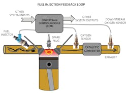
An automobile’s fuel-oxygen ratio determines performance as well as its exhaust toxicity, making it essential for vehicle designers to get this mixture right and keep it right over time. A proper mixture requires measurements from two oxygen sensors and other physical parameters such as fuel pressure, temperature, and crank speed. These measurements assist in the production of a continuous fuel-injector duty cycle (Fig. 1).
1. The PCM collects appropriate sensor and system data to control the fuel-injector duty cycle.
Specifically, to get the fuel-oxygen mixture right, the system requires two oxygen sensors, one each to detect the engine’s catalytic converter input and output exhaust oxygen concentrations. Along with other sensor data, the vehicle’s powertrain control module (PCM) takes input from the oxygen sensor and the engine to calculate and dynamically adjust the engine’s fuel-oxygen ratio.
The PCM internal microcontroller and powertrain sensing electronics require an insurance policy that closely monitors the power rails and execution timing to provide a health check. This design solution evaluates supervisory and watchdog-timer (WDT) ICs and explains their function as an engineering aid to help keep the automotive engine running safely, reliably, and smoothly.
Motivation for Proper Fuel-Oxygen Mixtures
Evolving emission standards have resulted in extensive discharge control technologies and techniques. A critical component to help meet emissions standards is the catalytic converter. The catalytic converter changes toxic gases and pollutants from an internal combustion engine into less toxic waste.
However, of the many variables, the fuel-oxygen ratio in the engine’s combustion chambers is the most crucial when controlling the vehicle’s toxic elimination ability. The photochemical reaction to the automotive combustion produces many secondary pollutants that cause eye and nose irritation and reduce visibility.
To the driver, a poor fuel-oxygen mixture may appear as a rough engine idle, a decrease in engine power output, or lower fuel efficiency. Furthermore, a rich mixture can produce poor fuel economy, sluggish acceleration, sooty or black sparkplugs, black muffler end pipes, or a strong smell of gasoline when the machine is at idle. If this mixture is off, it may also indicate a malfunctioning catalytic converter, which in turn can cause an increase in the vehicle’s output of carbon monoxide (CO) and the volatile organic compound (VOC) pollutants.
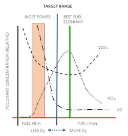
The use of stoichiometry quantifies the ratio of fuel-to-oxygen in the combustion chamber. Stoichiometry is the study of ratios or quantitative relationships between two or more substances undergoing a physical change or chemical reaction. For automobiles, a stoichiometric air-fuel ratio (AFR) or target range (blue line in Fig. 2) has the correct amount of fuel and air that’s as close as possible to a chemically complete combustion event (0% fuel, 0% oxygen, and minimal pollutants).
2. The x-axis shows the fuel-oxygen mixture and the y-axis indicates relative levels of pollutants.
The gasoline engine’s stoichiometric AFR is 14.7:1, which means 14.7 parts of air to one part of fuel. For alcohol and diesel fuel engines, the stoichiometric AFRs are 6.4:1 and 14.5:1, respectively.
An automobile that’s operating in a fuel-lean condition operates with the best fuel economy (green line in Fig. 2), but with high levels of nitrogen oxides (NOx) that expel through the tailpipe. An automobile in the fuel-rich zone operates with the most power (orange area in Fig. 2). This increase in power produces a high output level of CO and VOC pollutants.
Complete Fuel-Injection Picture
The fuel-injection system—including the fuel injector, PCM, sparkplug, two oxygen sensors, and the catalytic converter—monitors and controls the fuel-oxygen mixture throughout the combustion process.
The fuel-injection feedback loop controls the pulse-width algorithm for fuel injection events. A digital high signal initiates the fuel injector to send fuel into the combustion chamber. A digital low signal turns off the fuel injector. The fuel-injection system must meet many conditions, such as fuel-efficient cruising, an idling engine, a sudden acceleration, an uphill excursion or trailer towing, and extra fuel when the engine is cold.
Maintaining stable and optimal engine operation, despite these varying conditions, requires that more than 100 sensed events and parameters throughout the engine contribute to the fuel-injection PCM algorithm. These include air temperature, engine-coolant temperature, barometric pressure, throttle position, air flow, and engine load. However, the essential information in this system comes from the oxygen sensors.
The oxygen sensor’s probe is typically screwed into a threaded hole in the manifold. With older vehicles, the location of this threaded hole is upstream from the catalytic converter. Newer vehicles that meet U.S. regulations have a sensor before and after the catalytic converter.
A pulse-width signal from the PCM causes the fuel injector’s pressurized fuel to squirt into the combustion chamber. The upstream oxygen sensor located between the combustion chamber and the catalytic converter measures the exhaust’s oxygen concentration for the first time. The output fumes then travel through the catalytic converter, which filters many of the pollutants. After the catalytic converter, the second oxygen sensor again measures the oxygen concentration.
The engine control unit uses many lookup tables and a formula to determine the pulse width for given operating conditions. The following equation is a series of many factors multiplied by each other, many of which come from lookup tables. In this example, the equation has three factors, whereas a real control system might have 100 or more.
Pulse width = (BPW) x (A) x (B) x (C) (1)
where BPW = the base pulse width; A = Factor A; B = Factor B; and C = Factor C.
These factors are critical for the proper operation of the fuel-injection system. However, an insurance policy can be applied to ensure proper functioning of the fuel-injection system. A health check will validate that appropriate power levels are present and that the microcontroller’s calculated values and directives are accurate. A voltage supervisor/WDT combination acts as that insurance policy by monitoring and verifying power and microcontroller computations over the vehicle’s life.
PCM Stabilization Techniques
Automotive systems require several different voltage rails to power analog and digital circuitry. A few standard rail values are 1.2 V, 1.8 V, 2.5 V, and 3 V. For example, the MAX6746, MAX6747, MAX6748, MAX6749, MAX6750, MAX6751, MAX6752, and MAX6753 devices have ±2% factory-trimmed reset threshold voltages in approximately 100-mV increments from 1.575 to 5.0 V and/or adjustable reset threshold voltages using external resistors.
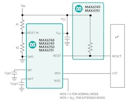
The MAX6746–MAX6753 low-power microprocessor (μP) supervisory circuits monitor single/dual-system supply voltages and provide external capacitor adjustability timeout for reset and watchdog functions (Fig. 3).
3. Resistor-dividers R1 and R2 set the voltage supervisor’s trip level at RESET IN.
In Figure 3, if RESET IN falls below the reset threshold (factory programmed), the RESET output pin lowers to ground to indicate that the power supply is below a safe operating value. Falling below this power-supply threshold can cause the attached ICs to malfunction.
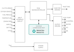
The RESET output remains asserted for the reset timeout period after RESET IN rises above the reset threshold. The reset function notifies the controller concerning this low-power condition (Fig. 4).
4. This gasoline management system features voltage supervisor/WDT insurance.
To prevent microcontroller malfunctions or runaway conditions, the WDT expects a periodic signal from a microcontroller in a specific timeframe. A continual microcontroller response ensures that the controller is operating properly (Fig. 5).
5. In this watchdog timing diagram, WDS = GND.
In Figure 5, the capacitor value on the SWT pin to ground determines the maximum timeout period (tWD) between the microcontroller pulses to the WDI pin. If the microcontroller misses a pulse, the WDT algorithm issues a reset notification. A missed microcontroller pulse indicates a microcontroller malfunction. The capacitor on the SRT pin to ground determines the reset timeout period (tRP). The RESET pin remains in the notification state until the microcontroller sends a valid transition to the WDI pin.
Conclusion
Voltage and execution monitoring play a critical role in the functional safety for all automotive electronics, including the fuel-injection process. In the machine’s fuel-injection feedback loop, the oxygen sensor measurements and over 100 other data quantities are combined in the PCM calculation to implement optimum emissions conditions. The insurance policy utilized by including supervisors and WDTs across all automotive systems safeguards circuit reliability and stability, which keeps vehicles moving on down the road.
